 |
Order
no.
|
Size
|
Support force F max.
[kN]
|
H
|
Stroke
[mm]
|
SW1
|
SW2
|
G
|
Weight
[g]
|
|
75416
|
M12
|
8
|
78-83
|
5
|
21
|
6
|
M12
|
939
|

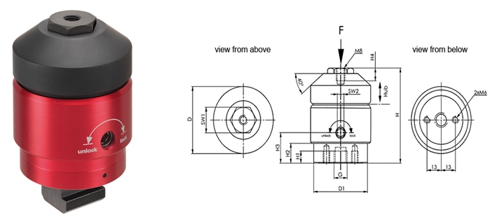
Application:
1. Fasten support element (2x M6 connecting thread) on fixture.
- Note operator side!
- Alternatively: Remove M12 x 10 threaded stud and replace with M12 x 30 threaded stud and mount the support element with key (size 21), e.g. for T-groove mounting
- (No defined operator side ensured).
2. Turning the clamping cam (hexagon socket size 6) on the outside surface of the red protective sleeve positions the supporting bolt against the workpiece with light spring force.
3. Turning further as far as it will go (lock) - a total of 180° - locks the clamping mechanism of the supporting bolt without length change. The support element is positioned on the workpiece and locked.
4. Turning in the opposite direction (unlock) releases the clamping. Continuing to turn back as far as it will go - a total of 180° - moves the supporting bolt to the end position.
Note:
- M8 thread on supporting bolt can be mounted with pressure screws (Nos. 7110DHX, 7110DIX, 7110DKX, 7110DFX).
- Customer-specific extensions can also be mounted.
- For reliable function the M12 threaded hole must always be closed.
Advantage:
- Used as an extra support to prevent sagging and vibration of the workpiece.
- Mounted directly under a clamping point, it prevents distortion of the workpiece.
- Compensation of large workpiece tolerances (castings).
Dimensions:
Order
no.
|
Size
|
D
|
D1
|
H1
|
H2
|
H3
|
H4
|
|
75416
|
M12
|
55
|
49.4
|
10
|
16
|
25
|
10.5
|
|
|
|


 STANDARD CLAMPING ELEMENTS